Force metrology determines the mechanical interaction that accelerates a mass (F = ma). The SI coherent unit is the Newton (1 N = 1 kg·m/s^2). In structural engineering and materials testing, forces are expressed in kilonewtons (kN) or pounds-force (lbf), where 1 lbf = 4.4482216152605 N based on standard gravity (9.80665 m/s^2).
1 N = 1 kg·m/s^2 = 10^5 dynes; 1 lbf = 4.4482216152605 N = 0.45359237 kgf; 1 kN = 1,000 N = 224.808943 lbf; 1 kip = 1,000 lbf = 4.448222 kN; 1 kgf (kilopond) = 9.80665 N = 2.204623 lbf; standard gravity g_n = 9.80665 m/s^2.
Key Takeaways & Core Facts
Essential metrology takeaways synthesized for researchers, engineers, and technical professionals.
Pound-force (lbf) is defined as the downward gravitational force exerted on one avoirdupois pound mass under standard international gravity (9.80665 m/s^2).
Universal testing machines (UTM) measure material yield strength and elongation by measuring tension via hermetically sealed foil strain gauge load cells.
One kilonewton (1 kN = 1,000 N) equals approximately 224.809 lbf, serving as the core unit for civil structural ratings and anchor bolt proof testing.
Secondary load cells require annual recalibration traceable to national primary deadweight force machines under ISO 7500-1 or ASTM E4 standards.
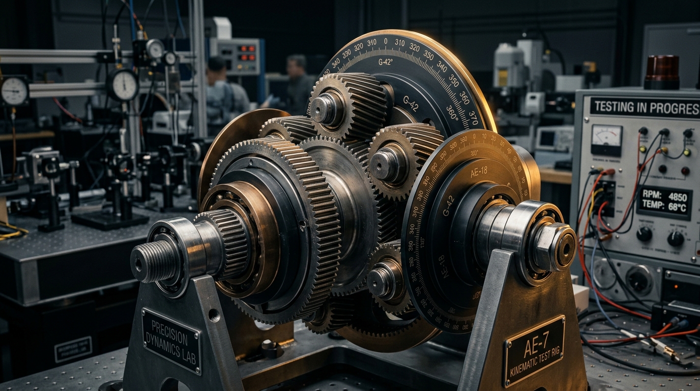
The Dynamical Definition of Force in Classical Newtonian Mechanics
Force represents the vector physical interaction that alters or tends to alter the motion, direction, or mechanical shape of a physical body. Sir Isaac Newton formulated this dynamical relationship in his 1687 masterwork Philosophiae Naturalis Principia Mathematica, establishing the Second Law of Motion: force equals the time rate of change of momentum, simplifying for constant mass to mass multiplied by acceleration ($F = m \cdot a$).
Within the International System of Units, force possesses the coherent derived unit of the Newton (N), named in honor of Isaac Newton. One Newton represents the exact force required to accelerate a mass of one kilogram at a rate of one meter per second squared ($1\text{ N} = 1\text{ kg}\cdot\text{m/s}^2$). Materials scientists and civil structural engineers converting tensile test data into customary engineering values utilize the force conversion portal to translate newtons, kilonewtons, pounds-force, and kips without precision loss.
The Customary Gravitational Unit: Pound-Force versus Pound-Mass
A persistent source of dimensional errors in structural engineering stems from conflating mass with force within customary imperial units. Under English engineering practice, the pound-mass (lbm) quantifies quantity of matter (0.45359237 kilograms), whereas the pound-force (lbf) represents the gravitational force acting on that mass.
To establish an unambiguous international standard, metrologists defined the pound-force as the gravitational downward force exerted on one avoirdupois pound mass situated in standard international gravity ($g_n = 9.80665\text{ m/s}^2$, or approximately $32.17405\text{ ft/s}^2$). Multiplying 0.45359237 kg by 9.80665 m/s² yields the exact international conversion constant: $1\text{ lbf} = 4.4482216152605\text{ Newtons}$. In large-scale structural engineering across North America, 1,000 pounds-force is designated as one "kip" ($1\text{ kip} = 1,000\text{ lbf} = 4.448222\text{ kN}$). For details regarding mass definitions, explore our analytical mass metrology paper.
Universal Testing Machines and Uniaxial Tensile Testing
Verifying the structural strength of metals, structural concrete, polymers, and aerospace composites requires destructive mechanical testing inside a Universal Testing Machine (UTM). A modern UTM features dual electromechanical drive screws or high-pressure servo-hydraulic actuators that pull a standardized tensile dogbone specimen under precise crosshead velocity control under ASTM E8 and ISO 6892 standards.
As the tensile crosshead displaces upward, an inline electronic load cell measures the resisting mechanical force, while a high-resolution contact clip-on extensometer or non-contact optical laser video extensometer measures specimen elongation. Dividing instantaneous tensile force by the specimen's initial cross-sectional area yields engineering stress ($\sigma = F / A_0$), while dividing elongation by initial gauge length yields engineering strain ($\epsilon = \Delta L / L_0$). To translate structural stress into equivalent hydrostatic pressure units, examine our pressure and mechanical stress converter.
Hooke's Law and Modulus of Elasticity Determination
During the initial phase of a tensile test, metallic alloys deform elastically: removing the applied tensile force permits the atomic crystal lattice to spring back completely to its original undeformed dimensions. Robert Hooke discovered in 1676 that within this linear elastic regime, mechanical stress is directly proportional to mechanical strain ($\sigma = E \cdot \epsilon$), where $E$ represents the Modulus of Elasticity, also known as Young's Modulus.
Young's Modulus quantifies an alloy's inherent mechanical stiffness. Structural carbon steel exhibits an elastic modulus near 200 Gigapascals (approximately 29,000,000 psi), while aerospace titanium alloys exhibit moduli near 114 Gigapascals (16,500,000 psi). As tensile loading intensifies, metals reach their yield strength—the threshold where atomic dislocations glide permanently through the crystal lattice, causing permanent plastic deformation. For tooling and linear component dimensions, examine our precision dimensional metrology guide.
Strain Gauge Load Cell Architecture and Wheatstone Bridges
High-capacity force measurement across universal testing machines, crane scales, and rocket engine thrust test stands relies on strain gauge load cells. A load cell consists of an engineered metallic spring element—typically fabricated from heat-treated alloy steel, aluminum, or precipitation-hardened 17-4 PH stainless steel—that deforms elastically and predictably under applied force.
Piezoresistive foil strain gauges are bonded securely to the spring element surfaces. These gauges consist of a microscopic etched constantan or karma alloy foil grid encapsulated in a polyimide carrier film. When mechanical tension stretches the foil grid, its electrical resistance increases; when compression shortens the grid, resistance decreases. Four matching strain gauges are wired into a balanced Wheatstone bridge circuit, converting minute fractional resistance shifts into a clean millivolt electrical signal proportional to applied force.
Force Unit Conversion Reference Matrix
Structural analysts, geotechnical engineers, and materials testing laboratories utilize precise conversion factors to coordinate structural loading calculations. The following reference table outlines standard multipliers linking SI, metric gravitational, and imperial force units:
| Force Unit | Newtons (N) | Kilonewtons (kN) | Pounds-Force (lbf) | Kips (kip) |
|---|---|---|---|---|
| 1 Newton (N) | 1.000000 N | 0.001000 kN | 0.2248089 lbf | 0.00022481 kip |
| 1 Kilonewton (kN) | 1,000.000 N | 1.000000 kN | 224.80894 lbf | 0.22480894 kip |
| 1 Meganewton (MN) | $10^6$ N | 1,000.000 kN | 224,808.94 lbf | 224.808943 kip |
| 1 Pound-Force (lbf) | 4.448222 N | 0.004448 kN | 1.0000000 lbf | 0.00100000 kip |
| 1 Kip (1,000 lbf) | 4,448.222 N | 4.448222 kN | 1,000.0000 lbf | 1.00000000 kip |
| 1 Kilogram-Force (kgf) | 9.806650 N | 0.009807 kN | 2.2046226 lbf | 0.00220462 kip |
| 1 Dyne (dyn) | 0.000010 N | $10^{-8}$ kN | $2.248 \times 10^{-6}$ lbf | $2.248 \times 10^{-9}$ kip |
Primary Force Realization: Deadweight Calibration Machines
While mass balances measure an object's mass in a resting state, force metrology requires realizing dynamic vector forces under controlled conditions. National Metrology Institutes like NIST maintain primary deadweight force calibration machines capable of applying forces up to one million pounds-force (4.45 Meganewtons). A deadweight machine consists of a vertical suspension stack holding dozens of calibrated stainless steel mass disks suspended inside a multi-story pit.
When the machine lowers a mass disk onto the loading frame, gravity acts on that mass to generate an exact downward vertical force ($F = m \cdot g_{\text{local}} \cdot [1 - \rho_{\text{air}} / \rho_{\text{mass}}]$), corrected for local gravitational acceleration and atmospheric air buoyancy. Deadweight calibration machines achieve measurement uncertainties below 0.001 percent (10 parts per million), providing the primary physical anchor for aerospace load cells and industrial crane safety scales. To explore mass calibrations and gravitational buoyancy corrections, consult our mass to force gravitational conversion guide.
ISO 7500-1 and ASTM E4 Machine Verification Standards
Universal testing machines operating across commercial testing laboratories must undergo annual calibration verification under ISO 7500-1 or ASTM E4 specifications. A certified calibration specialist mounts a traceable transfer standard—such as an ISO 376 Class 0.5 proving ring or multi-column compression load cell—inside the UTM test bay, applying five incremental force steps across three separate loading series.
The verification protocol evaluates machine repeatability, zero return error, and relative force indication error. Machines satisfying ISO 7500-1 Class 0.5 or Class 1 certification demonstrate relative force errors below plus or minus 0.5 percent or 1.0 percent across their verified working range. Operating within certified calibration limits guarantees that materials failure reports withstand scrutiny in aerospace quality audits and legal forensic investigations.
Cyclic Fatigue Testing and S-N Curve Metrology
Beyond static tensile failure, mechanical components operating inside aircraft airframes, railroad axles, and automotive suspension linkages frequently fracture under cyclic fluctuating stresses well below their static yield strength. Materials engineers execute fatigue testing using high-frequency servo-hydraulic or electromagnetic resonance testing machines under ASTM E466 standards. The machine subjects a polished test specimen to millions of alternating tension-compression cycles at frequencies up to 100 Hertz.
Plotting cyclic stress amplitude ($S$) against the logarithmic number of cycles to failure ($N$) produces the classical Wöhler S-N curve. Ferrous alloys typically exhibit a defined fatigue limit—an endurance threshold below which the metal withstands infinite stress cycles without microcrack propagation. Non-ferrous alloys such as aluminum lack a distinct fatigue limit, requiring finite life design based on cumulative damage calculations under the Palmgren-Miner rule.
Dynamic Force Metrology and High-Rate Impact Testing
Static force calibrations do not capture all physical behaviors: automotive crashworthiness testing, ballistic armor evaluation, and explosive metal forming subject components to violent dynamic impact forces lasting mere milliseconds. Under high strain rates, metals exhibit elevated yield strengths due to dislocation pileups within the crystal grains.
Dynamic force metrology utilizes piezoelectric quartz force transducers possessing resonant frequencies above 50 kilohertz. When an impact hammer strikes the quartz crystal, mechanical compression induces a surface electrical charge without measurable deflection. High-speed charge amplifiers convert these charges into voltage signals recorded by digital storage oscilloscopes, capturing peak impact forces exceeding 500 kilonewtons within microseconds. For comprehensive details regarding fluid hydrostatic pressures and Bourdon gauge mechanics, explore our industrial pressure standards guide.
Authoritative Metrological Standards Cited
All unit ratios, physical constants, and dimensional formulas in this paper are verified against official international standards repositories.