Angular metrology measures the circular divergence between two intersecting lines or rays. In the International System of Units, the radian (rad) is the dimensionless coherent unit, subtending an arc equal in length to the radius (2π rad = 360°). Astronomical and surveying instruments utilize sexagesimal arcseconds (1° = 60′ = 3,600″).
2π rad = 360° (exact); 1 rad ≈ 57.295779513°; 1° = π/180 rad ≈ 0.017453293 rad; 1 arcmin (′) = 1/60° ≈ 0.000290888 rad; 1 arcsec (″) = 1/3600° ≈ 4.8481368 × 10^-6 rad; 1 gradian (gon) = 0.9° = π/200 rad; 1 mil (NATO) = 1/6400 circle.
Key Takeaways & Core Facts
Essential metrology takeaways synthesized for researchers, engineers, and technical professionals.
The radian links linear displacement directly to circular arcs through s = rθ, eliminating arbitrary sexagesimal base-60 conversion constants in physics and engineering.
One arcsecond represents 1/3600 of a degree (approximately 4.848 × 10^-6 radians), subtending just 4.85 millimeters of lateral displacement at a distance of 1 kilometer.
Optical autocollimators measure minute angular deflections of machine tool ways down to 0.01 arcseconds by projecting collimated light onto optical mirrors.
Surveying theodolites and total stations measure horizontal azimuths and zenith angles, compensating for instrumental tilt errors via dual-axis liquid electronic compensators.
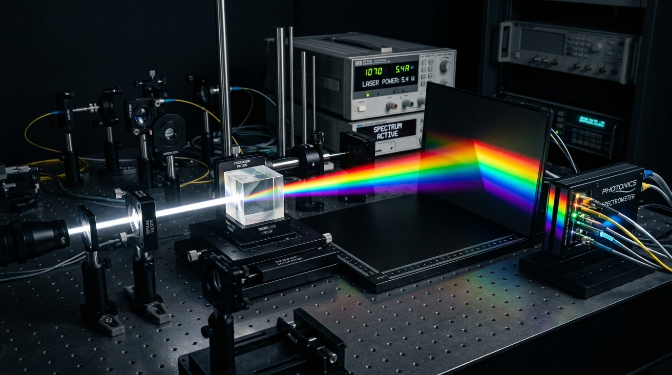
Planar Divergence and the Dimensionless SI Radian
Angular metrology evaluates the ratio of circular arc length to radius between two intersecting lines radiating from a common vertex. Unlike base physical dimensions such as mass or length, planar angle occupies a unique status within the International System of Units. In 1995, the 20th General Conference on Weights and Measures formally classified the radian (rad) as a dimensionless derived unit, defined algebraically as the ratio of two lengths: arc length divided by radius ($\theta = s / r$).
Because the radian directly equates linear distance along an arc to angular subtension, it serves as the natural mathematical language for calculus, rotational dynamics, wave propagation, and electromagnetic physics. One complete circular rotation encompasses exactly $2\pi$ radians ($6.283185\text{ rad}$). Applied metrologists, surveyors, and optical engineers regularly utilize the angle conversion portal to translate radians, sexagesimal degrees, centesimal gradians, and military milliradians across high-precision calculation routines.
The Sexagesimal Tradition: Degrees, Arcminutes, and Arcseconds
While the radian dominates theoretical physics, practical geodesy, navigation, and observational astronomy continue to employ the sexagesimal base-60 system inherited from ancient Babylonian astronomy. The circle subdivides into 360 degrees ($360^\circ$), with each degree dividing into 60 minutes of arc (arcminutes, $60'$) and each arcminute dividing into 60 seconds of arc (arcseconds, $60''$).
One arcsecond ($1''$) represents an extraordinarily minute angular divergence, equal to $1/3600$ of a degree or approximately $4.848137 \times 10^{-6}$ radians. At a distance of one kilometer, an angular shift of one arcsecond subtends a lateral displacement of only 4.85 millimeters. In astronomical navigation and stellar astrometry, ground-based optical telescopes utilize arcseconds and milliarcseconds to calculate stellar parallax baselines and planetary proper motions. To examine how angular navigation coordinates interface with terrestrial aircraft velocities, explore our aerodynamic velocity and navigation guide.
Centesimal Gradians and Military Milliradians
During the French Revolution, metrologists attempted to decimalize circular measurement by introducing the gradian (also designated the gon or grade). The gradian system divides a right angle into exactly 100 gradians, producing 400 gradians in a full circle. While adopted in civil tunneling and cadastral surveying across parts of continental Europe, the gradian never supplanted the sexagesimal degree in worldwide maritime or aviation navigation.
In ballistic engineering and tactical optical sights, defense forces deploy the milliradian (abbreviated mrad or mil). An exact mathematical milliradian ($0.001\text{ rad}$) subtends exactly one meter of lateral target width at a distance of 1,000 meters. NATO forces approximate this relationship by standardizing 6,400 mils per circle (rather than the true mathematical $2,000\pi \approx 6,283.185\text{ mrad}$), providing an easily divisible integer grid for artillery azimuth laying and optical rangefinder reticles.
Optical Autocollimators and Precision Angle Realization
Manufacturing ultra-precise machine tool slideways, optical prisms, and coordinate measuring machine guide rails requires detecting angular pitch and yaw errors down to fractions of an arcsecond. Mechanical levels cannot resolve such minute deflections; metrology laboratories deploy optical autocollimators. An autocollimator combines an illuminated collimator telescope and an optical viewing reticle within a single rigid barrel.
The instrument projects a beam of parallel, collimated light rays toward a flat optical mirror mounted on the component under inspection. If the mirror tilts by a minute angle ($\theta$), the reflected light beam re-enters the objective lens at an altered angle, focusing onto a calibrated photodiode array or CMOS sensor displaced by a distance: $d = 2 f \theta$, where $f$ represents the focal length of the objective lens. Modern electronic autocollimators measure angular deflections with resolutions down to 0.005 arcseconds, providing primary calibration traceability for high-precision rotary indexing tables.
Theodolites, Total Stations, and Axis Collimation Errors
Geodetic boundary surveys measure horizontal azimuths and vertical zenith angles across terrain using digital optical theodolites and total stations. A total station integrates an electronic digital theodolite with an infrared Electro-Optical Distance Meter (EDM), mounting a precision optical telescope across two orthogonal axes: a vertical standing axis and a horizontal trunnion axis. Radial optical glass encoders etched with incremental chrome grating patterns detect angular rotations with sub-arcsecond electronic resolution.
Field instruments must compensate for three systematic mechanical alignment imperfections: vertical axis tilt error, horizontal collimation error (where the optical sighting line fails to reside perpendicular to the trunnion axis), and trunnion axis tilt error. Modern robotic total stations incorporate dual-axis liquid-surface electronic tilt sensors. The instrument continuously measures its own physical mislevelment relative to the local gravity vector, applying real-time trigonometric corrections to recorded horizontal and zenith angles under ISO 17123-3 testing standards. For complementary cadastral area calculations, consult our geodetic surveying and land area paper.
Angular Unit Conversion Reference Matrix
Engineers, geodetic cartographers, and optical physicists require exact mathematical conversion constants to bridge dimensionless radians, sexagesimal degrees, and tactical angular units. The following reference table outlines fundamental conversions established across international standards:
| Angular Unit | Radians (rad) | Degrees (°) | Arcseconds (″) | Gradians (gon) |
|---|---|---|---|---|
| 1 Radian (rad) | 1.000000 rad | 57.295780 ° | 206,264.81″ | 63.66198 gon |
| 1 Degree (°) | 0.017453 rad | 1.000000 ° | 3,600.00″ | 1.11111 gon |
| 1 Arcminute (′) | 0.000291 rad | 0.016667 ° | 60.00″ | 0.01852 gon |
| 1 Arcsecond (″) | $4.8481 \times 10^{-6}$ rad | $2.7778 \times 10^{-4}$ ° | 1.00″ | $3.0864 \times 10^{-4}$ gon |
| 1 Gradian (gon) | 0.015708 rad | 0.900000 ° | 3,240.00″ | 1.00000 gon |
| 1 Milliradian (mrad) | 0.001000 rad | 0.057296 ° | 206.26″ | 0.06366 gon |
| 1 Full Circle (rev) | $2\pi$ rad (6.283185) | 360.000000 ° | 1,296,000.0″ | 400.00000 gon |
Small Angle Approximation in Mechanical Engineering
When analyzing minute angular deflections across elastic machine tool structures, optical mounts, and civil bridges, engineers frequently utilize the small-angle approximation. Derived from the Taylor series expansion of trigonometric functions ($\sin \theta = \theta - \frac{\theta^3}{6} + \dots$ and $\tan \theta = \theta + \frac{\theta^3}{3} + \dots$), when an angle $\theta$ is expressed in radians and remains small ($\theta < 0.1\text{ rad}$, or roughly $5.7^\circ$), the sine and tangent functions equal the angle itself ($\sin \theta \approx \theta$ and $\tan \theta \approx \theta$).
Similarly, the cosine of a small angle approximates $1 - \frac{\theta^2}{2}$. Applying the small-angle approximation simplifies non-linear differential deflection equations into clean linear algebraic relationships, accelerating structural deflection modeling and finite element analyses. Optical beam path calculations utilize trigonometric baseline lengths to project lateral spot displacements over long optical propagation benches.
Diffraction Limits and the Rayleigh Criterion
In optical imaging systems, the minimum resolvable angular separation between two close point light sources—such as adjacent stars or microscopic features on a semiconductor lithography mask—is physically limited by optical wave diffraction. When parallel light waves pass through a circular telescope aperture of diameter $D$, diffraction patterns form an Airy disk consisting of a central bright spot surrounded by concentric dark and bright rings.
Lord Rayleigh formulated the criterion for optical resolution in 1879, establishing that two point sources are just barely resolved when the central maximum of one Airy disk coincides with the first minimum of the other. Expressed mathematically: $\theta_{\text{min}} = 1.22 \frac{\lambda}{D}$, where $\lambda$ is the optical wavelength and $D$ is aperture diameter. Achieving sub-arcsecond angular resolution in astronomical observatories requires large primary mirrors or multiple baseline optical interferometers. For electromagnetic wavelength equations governing diffraction limits, explore our electromagnetic frequency and wave metrology paper.
Primary Angular Calibration via Angle Gauge Blocks
Similar to linear gauge blocks, primary angular metrology utilizes angle gauge blocks fabricated from hardened tool steel, tungsten carbide, or low-expansion glass ceramics. An angle block set contains thirteen precision wedges ground to exact angular steps spanning from one arcsecond up to 45 degrees. By combining multiple wedges in additive or subtractive stacking arrangements, technicians assemble hundreds of thousands of discrete angular calibration references.
Calibrating angle gauge blocks requires full-circle closure methods using dual electronic autocollimators and indexing tables. Because the sum of all interior angles around a complete circle must equal exactly 360 degrees ($2\pi$ radians), full-circle closure eliminates external reference dependencies, enabling primary laboratories to calibrate angle standards from pure mathematical geometry. Mastering angular metrology provides the geometric foundation for aerospace guidance platforms, satellite optical payloads, and global geodetic mapping arrays. For complementary cadastral area calculations, consult our surveying area calculations portal.
Authoritative Metrological Standards Cited
All unit ratios, physical constants, and dimensional formulas in this paper are verified against official international standards repositories.


